Introduction
What's better than an airplane with one engine? An airplane with two engines of course. However, with more power comes more responsibility and understanding. First off, you'll find that there are a few new V speeds that you aren't used to with single engine airplanes. The speed we will focus on is Vmc. Vmc is the minimum controllable airspeed at which directional control can be maintained with the critical engine inoperative. Oh boy, so what's the critical engine then? The Critical Engine is the engine that when failed most adversely affects the performance and handling qualities of the airplane (FAR 1.1). To break it down further, think of the critical engine as being the engine that will cause the most trouble for you if it were to fail.
Now that we have all that out of the way, lets start thinking about this a little more. In a single engine plane, the engine is in the center of the plane. Thus if the engine goes out, the only forces you have is a loss of thrust in the center of the aircraft (and of course lift). Now lets think of a multi-engine aircraft with an engine on each wing. When you lose one engine, you will experience all sorts of different forces acting against you. You will experience different performance and handling qualities depending on which engine fails. We've discussed the definition of a critical engine, lets discuss how we determine which engine is the critical engine.
Determining Critical Engine
To determine which of the engines is the critical engine, we need to look at 4 aerodynamic factors: P-Factor, Accelerated Slipstream, Spiraling Slipstream, and Torque. An easy acronym to remember this is PAST. Each of these will help us understand which engine creates the most adverse effect and why. Each factor is assuming we are talking about a conventional twin, meaning both engines spin in the clockwise direction (we will discuss non-conventional twins later).
P-Factor (Yaw)
You learned about P-Factor when you were learning about the left turning tendencies of a single engine aircraft. This is the same aerodynamic factor and concept, but lets see how it effects a multi-engine aircraft.
At low speeds and high angles of attack (like take-off), the descending blade (right blade) produces more thrust then the ascending blade (left blade), as shown by the light blue arrows in image 1. The descending blade on the right engine has a longer arm from the CG than the descending (right) blade of the left engine, creating a yaw force to the left.
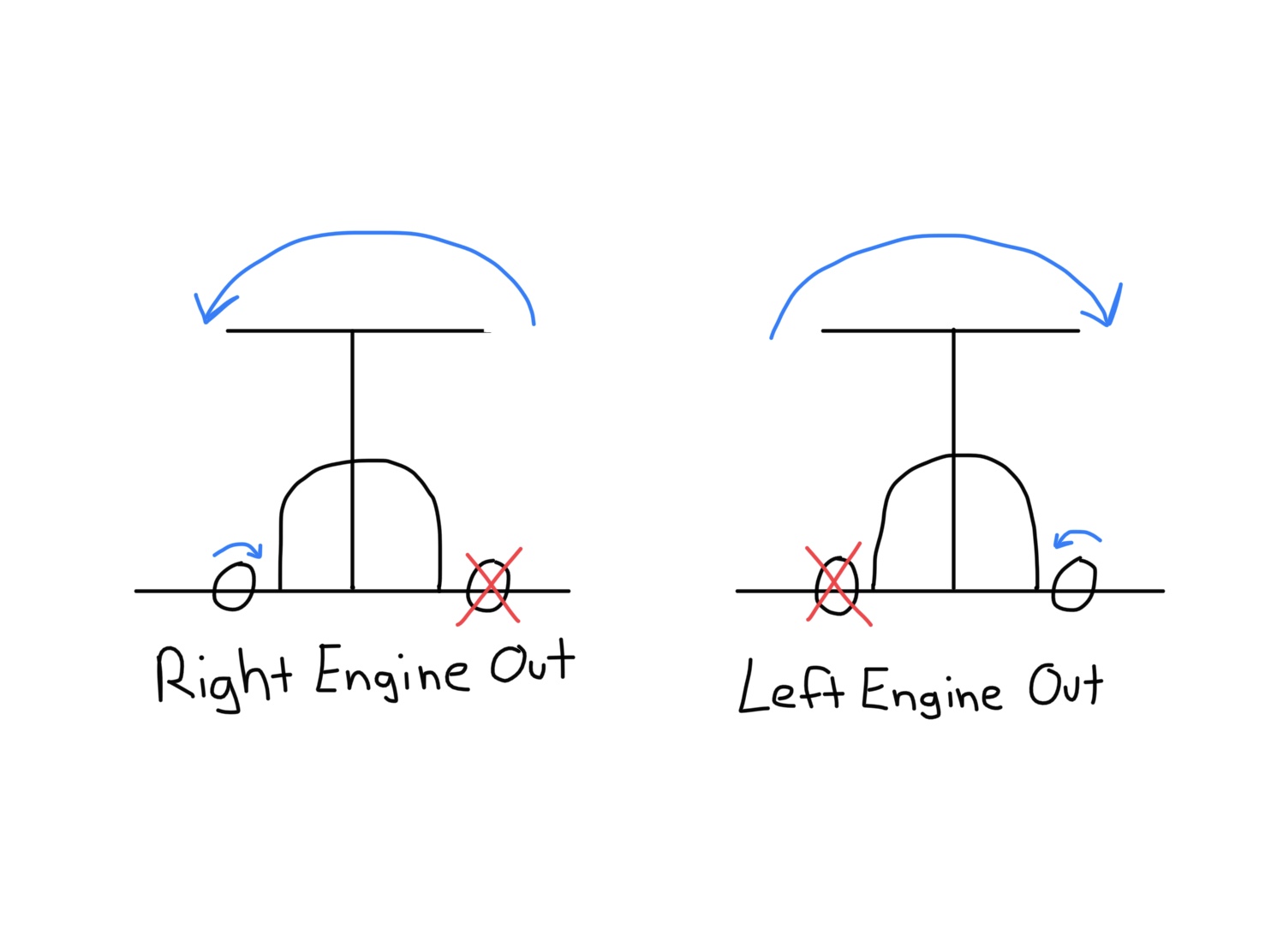
P- Factor causes a conventional twin to yaw to the left. If you look at image 2, you will see the effects of P-factor when each of the engines is inoperative. Failure of the left engine will cause more loss of directional control than the loss of right engine because of the longer arm of the right engine's thrust from the CG. The yaw produced by the left engine being inoperative will be greater than the yaw produced by the right engine being inoperative, making the left engine the critical engine.
For more information, watch this Video.
P-Factor Image 1 (Both Engines Operative)
P-Factor Image 2 (With Each Engine Inoperative)
Accelerated Slipstream (roll)
Now that we understand what P-factor is, we can better understand accelerated slipstream, since it is produced by P-factor.
As a result of P-factor, stronger induced lift is produced on the descending blade by its prop wash. The image shows the amount of induced lift with the light blue arrows. The greatest induced drag on the right wing, is further from the CG that the greatest induced drag on the left wing. This creates a rolling effect to the left.
Now lets look at what happens when each of the engines are inoperative. Image 2 shows the amount of rolling force depending on which engine is inoperative. As you can see, when the left engine is inoperative, the amount of greatest induced lift on the wing is further from the CG, which causes a greater rolling force than it does when the right engine is inoperative. The roll produced by the loss of the left engine will be greater than the roll produced by the loss of the right engine, making the left engine the critical engine.
For more information, watch this Video.
Accelerated Slipstream Image 1 (Both Engines Operative)
Accelerated Slipstream Image 2 (With Each Engine Inoperative)
Spiraling Slipstream (Yaw)
The spiraling slipstream may be a little bit easier to undertand. First we have to understand why spiraling slipstream goes in the direction it does. Remember when we talked about how the descending blade created more thrust? Well, That extra thrust on the descending blade is causing a lower pressure than the thrust created from the ascending blade. So the ascending blade had a higher pressure and what do we know about high and low pressure? Well, high pressure always goes towards low pressure.
So looking at image 1, we can see that the spiraling slipstream is going towards the right. That is because the high pressure from the ascending blade is moving towards the low pressure from the descending blade. Ok, now that we can see and understand that, lets take a look at what happens when each engine is inoperative.
When the right engine is inoperative, the spiraling slipstream from the left engine hits the vertical stabilizer from the left, which helps counteract the yawing motion towards the inoperative engine. When the left engine is inoperative, the spiraling slipstream from the right engine doesn't hit the vertical stabilizer and doesn't counteract that yawing motion into the inoperative engine. This causes a greater loss of directional control, making the left engine the critical engine.
For more information, watch this Video.
Spiraling Slipstream Image 1 (Both Engines Operative)
Spiraling Slipstream Image 2 (With Each Engine Inoperative)
Torque (Roll)
For every action there is an opposite an equal reaction (Newton 3rd law of motion). As a result of the propellers turning clockwise on a conventional twin, there is a left rolling tendency of the airplane. If the right engine fails, this left roll tendency will help us maintain control and resist the roll towards the right, inoperative engine, caused by asymmetric thrust. If the left engine fails, the left roll tendency by torque will add to the left turning force caused by asymmetric thrust into the inoperative engine. This makes it much more difficult to maintain directional control, making the left engine the critical engine.
For more information, watch this Video.
Torque
Critical Engine on a Non-Conventional Twin
So we've discussed the aerodynamic factors of a conventional twin and which engine would be the critical engine. However, not all multi-engine aircrafts are conventional. Aircrafts such as the Seminoles are non-conventional twins. The engines are counter rotating, meaning they rotate into each other. The left engine rotates clockwise, while the right engine rotates counter clockwise. The same aerodynamic factors apply to these aircrafts, but they have different effects, so lets take a look at each one.

P-Factor
The length of the arm from the greatest thrust is the same whether the left or the right engine are inoperative. Meaning, neither the left nor the right engine will have any more adverse effect than the other. The effects will be the same.

Accelerated Sliptream
The length of the arm from the greatest induced lift is the same whether the left or the right engine are inoperative. Meaning, neither the left nor the right engine will have any more adverse effect than the other. Failure of either engines will result in the same loss of control.

Spiraling Slipstream
As you can see by the image, because the right engine is rotating counter clockwise, the low pressure is now on the left side of the engine. This now creates a senecio where no matter what engine is inoperative, they will both have a spiraling slipstream towards the vertical stabilizer.
Torque
No matter which engine is inoperative, torque will oppose the roll created by asymmetric thrust.
After seeing how these aerodynamic forces act on a counter rotating multi-engine aircraft, we can see that there is no critical engine. It doesn't matter which engine we lose, the effects will be the same whether the left or right engine is inoperative.
Check out these recommended books:


Factors That Affect Vmc Speed
We've already talked about the definition of Vmc. We know it is the minimum controllable airspeed at which directional control can be maintained with the critical engine inoperative. Just like other V speeds, we know that the actual speed will vary with different factors. So how do aircraft manufacturers come up with this speed and what are the factors that change it? The acronym I like to use to remember this is SMACFUM. First lets talk about the factors used by manufacturers to determine the aircrafts published Vmc speed, then we will break them down and talk about how each of those factors affects the actual Vmc speed.
Standard Day at Sea Level
Most Unfavorable Weight
Aft CG
Critical Engine Windmilling
Flaps Takeoff Position/Landing Gear Up
Up to 5 Degrees Bank
Max Power in Operating Engine
Standard day at Sea Level
As we already know from previous knowledge of density altitude and single engine aircrafts, engine performance decreases as density altitude increases. When the operating engine has more performance, it will have more asymmetrical thrust into the inoperative engine. This causes you to need more rudder input to counteract the yaw from that asymmetric thrust. Resulting in an increase in airflow (airspeed) over the needed to maintain directional control. As density altitude increases, performance will decrease and Vmc will decrease. Making a standard day at seal level be your worst case scenario where Vmc will be the highest.
Most unfavorable weight
Unfavorable weight is light. The heavier the airplane, the lower the aircraft’s Vmc. The lighter the airplane, the higher the aircraft’s Vmc.
Aft CG
When you have an aft CG, the arm between the CG and the rudder is shorter, which means the rudder will be less effective. A higher airspeed would be required to counteract the yaw into the inoperative engine. So with an aft CG, the Vmc speed increases and a forward CG would decrease Vmc.
Critical engine wind milling
When the critical engine is windmilling, it will create more drag than if it was feathered. This will raise your Vmc speed. In turn, once you feather that propeller, you decrease the Vmc.
Flaps takeoff position/Landing gear up
We will break this down further into the two sections of flaps and gear. When flaps are out, they help stabilize the aircraft, which helps reduce Vmc. On the reverse side of that, we have less stabilization when flaps are up (in takeoff position), which increases our Vmc. Looking at the landing gear now, by lowering the gear we creating the “keel effect” which helps keep the aircraft straight. The accelerated slipstream behind the engine at full power encounters the gear and creates excess drag and that drag helps to counter the turning tendency. So both flaps up and gear up will negatively affect your Vmc speed.
Up to 5degrees Bank
When one engine is failed and you have wings level with the ball centered, you will actually be in a mild side-slip because the failed engine is causing drag and a loss of lift. By turning to up to a 5 degree bank toward the operating engine, you will decrease the drag causing a better climb performance and improve performance, as well as decrease Vmc.
Max power
This goes along with the same idea we discuss when we talked about standard day at sea level. The more power you have in your operating engine, will give you more performance in your operating engine causing more yaw into the inoperative engine. This will again, as explained before, require more rudder input to counteract that yaw. We will need to have more airflow (airspeed) to have more effectiveness of the rudder. We can now say that with more power, we will both increase our engine performance and increase our Vmc speed. Making max power our worst case scenario and Vmc will be at its highest.
How to do the Vmc Demo in the Piper Seminole
The objective of the Vmc Demo is to teach the student how to recognize and recover from a loss of directional control. You know you have lost directional control when you have full rudder deflection into the operating engine and the aircraft begins to yaw toward the inoperative engine.
Clearing turns
Flaps-up, gear-up
Slowly close left throttle while maintaining heading and altitude.
Mixtures–Enrichen, Props–Fwd, Fuel Pumps–On
Slow to 100 KIAS (approx. 10 KIAS above VYSE)
Slowly increase right throttle (operating engine) to full power. Use rudder to maintain directional control and bank up to 5 ̊ towards the operating engine.
Increase pitch attitude slowly, decrease airspeed at approximately 1 knot per second until full rudder is applied to maintain directional control.
Recover at 1st sign of:
Loss of directional control.
First indication of stall (stall horn or buffet)
Recover promptly by simultaneously reducing power sufficiently on the operating engine while decreasing the angle of attack as necessary to regain directional control within 20 ̊ of entry heading.
Continue recovery by increasing power slowly on operating engine while maintaining an AOA that allows for airspeed to increase to a point where directional control can be maintained with a minimum loss of altitude
Accelerate to 82-88 KIAS
Bring throttles slowly together to 20" MP
“Cruise Checklist.”